PRESERVE
Overview
The main aim of PRESERVE is to design, implement and test a secure and scalable V2X security subsystem for realistic deployment scenarios. PRESERVE will combine and extend results from earlier projects, and integrating and developing them to a pre-deployment stage by enhancing scalability. It reduces the cost level and focuses on deployment issues. It aims at protection ranging from the vehicle sensors using the on-board network and V2V/V2I communication. So, preserve will provide a complete, scalable and cost efficient V2X security subsystem according to the demand of market.
Objectives
-
To create an integrated V2X security Architecture (VSA) and design, implement and test a close to market implementation and is known as V2X security subsystem.
-
To prove that the performance and cost requirements that are provided for VSS occurring in current FOTs and their product deployment should be met by the VSS.
-
It provides a ready –to- use VSS implementation and that supports FOTs and provides a security solution.
-
It solves the technical issues that hinders the standardization and product pre-deployment.
PRESERVE

Project Status
Completed
CONTACT
Dr. Frank Kargl | University of Twente | The Netherlands
P.O.-Box 217, 7500 AE Enschede, The Netherlands
Phone: +31 53 489 4302
Email: f.kargl@utwente.nl
Partners
-
University of Twente
-
escrypt GmbH — Embedded Security
-
Fraunhofer Institute for Secure Information Technology — SIT
-
Fraunhofer Institute for Applied and Integrated Security — AISEC
-
KTH — Kungliga Tekniska högskolan
-
Renault
-
Trialog
Inputs
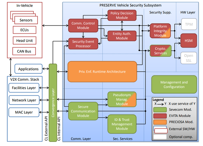
Architecture
Preserve V2X Communication Architecture

Vehicle Security Architecture
In vehicle infrastructure
-
Network layer routing table: The routing table stores information about the location of neighboring nodes in combination with a timestamp of the node’s latest update. The table entries are created based on position and time information from incoming messages. It is assumed that the geographic routing is executed on network layer of the communication stack. This also implies that the network header of the message has to contain mobility information (i.e. node ID, position, timestamp). Manipulation of the table content may cause routing attacks as wormhole or relay attacks, or possibly facilitate DoS (e.g., black- or gray-hole attacks).
-
Local Dynamic Map (LDM) on facilities layer: The LDM can be assumed to be a container that collects and manages all incoming messages. All applications running on the ITS-S can access this central storage in order to use a consistent base of data. It is assumed that this LDM is responsible for filtering duplicates or deleting outdated messages. As applications on application layer accesses this system, it is assumed that the LDM is operated on facilities layer. Manipulation of the LDM content may cause attacks related to traffic safety and traffic efficiency application.
-
Local station information on facilities layer (VIN, manufacturer, model, etc.):It is assumed that local station information is available and accessible to the application layer. Manipulation of this data may cause problems to the applications running at neighboring nodes. If, for example, local station dimensions at vehicle A are manipulated and subsequently broadcasted, traffic safety applications on vehicle B receiving this data may calculate false advice, warning, or reaction. Furthermore accessing sensitive, identifying information by malicious applications can cause privacy infringements.
-
Application Unit (AU) / Head Unit (HU): It is assumed that the HU consists of an HMI, the navigation system and telephone applications. Additionally, it is reasonable that Consumer Electronic devices are connected to the HU. Manipulation of the HU by attacks could cause bogus advisories for the driver.
-
Communication & Control Unit (CCU): The CCU is a central router for different communication links such as ITS G5A/B/C and ITS IMT Public.
-
Electronic Control Unit (ECU): An ECU combines an on-board sensor concentrator for some components as Power train, Chassis & Safety or Body Electronics.
-
Sensor: On-board sensors are controlled and managed by ECUs.
Nomadic devices are stand-alone systems that can be used either in vehicles or by other traffic participants like bicyclists as a sender of regular position information and as a receiver of V2X messages. It is further assumed that such a device has no connection to the ITS-S on-board system. Here-I-Am devices would only be able to send CAMs with the current position and timestamp.
From the view point of the security, a nomadic device that is actively participating in the V2X communication may be more attractive for attackers that attempt to extract secret keys in order to use them afterwards for different attacks.
Road side Infrastructure
A Roadside Unit consists in general of the same elements as a vehicle. The communication stack and the applications are probably very comparable with the vehicle station but the internal network may look different. A vehicle is connected with its Powertrain, Chassis & Safety and Body Electronic whereby a RSU is connected to road sensors (e.g. induction loops, cameras) and a back-end control center.
-
Network layer routing table.
-
Local Dynamic Map (LDM) on facilities layer.
-
Local station information on facilities layer (serial number, operator..)
-
Application Unit (AU)
-
Communication and control Unit (CCU)
-
Electronic Control Unit (ECU) combines on-board sensor concentrator such as Powertrain, Chassis & Safety and Body Electronic.
-
Sensors.
Data processing hub
Back-end Systems
-
Public key infrastructure (PKI)
-
Traffic Management Centre.
-
Roadside unit Management.
-
E-call service center.
Communication Protocol
IEEE 802.11p based G5A, G5B & G5C protocols with G5A and G5B frequencies reserved for traffic
Safety and efficiency relevant message exchange.
-
G5A and G5B for V2V and V2I interactions.
-
G5A for I2I interactions.
-
G5C for non-safety critical functions.
-
IMT public.
Achievements/Benifits
Transparent Communication:
-
Unique action ID
-
Cancelation Flag that indicates the explicit cancelation of a message with the same action
-
IDs from the same originator
-
Generation Time as reference for message content
-
Validity Duration defines the time span after generation Time when the message shall be deleted from all databases
-
Reference Position that provides optionally position and heading of the originator
-
Application Packet Type that defines the packet type in the payload
Physical Security :
-
Physical protection against eavesdropping of the wireless communication channels.
-
Physical integrity protection of transmitted data over the air.
-
Physical protection against manipulation of vehicular hardware components (e.g. sensors, ECUs, communication buses). However, critical building blocks of the PRESERVE VSS have to be protected against physical access and manipulation.
-
Physical resistance against premeditated destruction (e.g. vandalism)
-
Protection against physical access and theft.
Services
-
Harmonized V2X Security Architecture.
-
Implementation of V2X Security Subsystem.
-
Cheap and scalable security ASIC for V2X.
-
Testing results VSS under realistic conditions.
-
Research results for deployment challenges.
Limitations
-
Frequent communication disruptions due to the high mobility of ITS Vehicle Stations.
-
Channel bandwidth to be shared between all entities within communication range.